Ac Thermostat Wiring Diagram / Furnace Thermostat Wiring and Troubleshooting - HVAC How To / The thermostat wiring on these systems can have very similar wiring properties.
Get link
Facebook
X
Pinterest
Email
Other Apps
Ac Thermostat Wiring Diagram / Furnace Thermostat Wiring and Troubleshooting - HVAC How To / The thermostat wiring on these systems can have very similar wiring properties.. Of course if in doubt be sure to call a professional. Conventional heating/cooling systems wiring diagrams: Unsure if honeywell home thermostats from resideo are compatible with your home? Use our tool to determine which thermostats work with your home's existing wiring. Air compressor capacitor wiring diagram before you call a ac repair man visit my blog for some tips on how to save thousands in ac repairs.
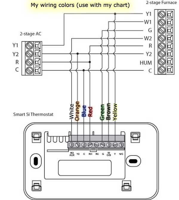
The terminals are usually marked 'r' and 'w'. Shows actual uses for most commonly seen wire colors in 4 wire units. Our page top sketch, courtesy of honeywell controls, illustrates the wiring diagram for a traditional honeywell. Unsure if honeywell home thermostats from resideo are compatible with your home? Refer to the control diagrams in appendix a.
Replacing the Coleman Mach thermostat with an Ecobee from janeandjohn.org In thermostat switch we have two types of connection, in which one is for main and in the above diagram i shown how to wire a ref thermostat, but this only a basic diagram and we will publish complete refrigerator diagram soon. The following diagrams show all of the common wiring scenarios you are likely to encounter. Terminal 05 is usually the supply wire to the ac compressor, taking a yellow wire. The common lead of the transformer. Here is a link to the wiring diagram for my heat pump. Shows actual uses for most commonly seen wire colors in 4 wire units. Colors, terminals, functions, voltage path! Whether you are designing a simple thermostat or a smart thermostat complete with intuitive hmi and secure wireless connectivity, our reference designs and integrated circuits help you address complex challenges and deliver what's next in thermostat design.
Unsure if honeywell home thermostats from resideo are compatible with your home?
Colors, terminals, functions, voltage path! They usually operate at 24v ac power, and the source of this control power comes from a control. Here is a link to the wiring diagram for my heat pump. Furnace thermostat wiring falls in the diy category that a handy type person can hook up or fix. Of course if in doubt be sure to call a professional. Always refer to your thermostat or equipment installation guides to verify proper wiring. Marine accommodation air conditioner piping diagram. Shows actual uses for most commonly seen wire colors in 4 wire units. Thermostats use 24 volts ac from a transformer to control a. Ecobee thermostat installation with an isolation relay. This article series explains the basics of wiring connections at the thermostat for heating, heat pump, or air conditioning systems. Refer to the control diagrams in appendix a. The common lead of the transformer.
Air compressor capacitor wiring diagram before you call a ac repair man visit my blog for some tips on how to save thousands in ac repairs. Nest thermostat connectors wiring diagrams: Whether you are designing a simple thermostat or a smart thermostat complete with intuitive hmi and secure wireless connectivity, our reference designs and integrated circuits help you address complex challenges and deliver what's next in thermostat design. This thermostat circuit compromises of a voltage divider circuit and output on and off switching circuit. Always refer to your thermostat or equipment installation guides to verify proper wiring.
Wiring Diagram for thermostat to Furnace Sample from worldvisionsummerfest.com The thermostat wiring on these systems can have very similar wiring properties. Diagrams are available for all warmup thermostats whether you are installing it as part of a. Apakah setiap ac wiring dasarnya seperti itu ? Always refer to your thermostat or equipment installation guides to verify proper wiring. All furnace switched components have one side of their power connected to this lead. Nest thermostat connectors wiring diagrams: Thermostat installation & wiring diagrams. Our page top sketch, courtesy of honeywell controls, illustrates the wiring diagram for a traditional honeywell.
In this article, i am going to explain the function and wiring of the most common home climate control thermostats.
Air compressor capacitor wiring diagram before you call a ac repair man visit my blog for some tips on how to save thousands in ac repairs. Colors, terminals, functions, voltage path! As shown in the diagram, you will need to power up the thermostat and the 24v ac power is connected to the r and c terminals. This diagram is to be used as reference for the low voltage control wiring of your heating and ac system. If a thermostat is thought to have a problem then it can be bypassed with a jumper wire. Gives honeywell thermostat wiring diagram 4 wire guides and hints. Heat pump thermostat wiring explained! But an important issue here is that the diagrams and. In this article, i am going to explain the function and wiring of the most common home climate control thermostats. This article series explains the basics of wiring connections at the thermostat for heating, heat pump, or air conditioning systems. Furnace thermostat wiring falls in the diy category that a handy type person can hook up or fix. Insert the stripped harness wires into the thermostat terminals according to your wiring diagram. Always refer to your thermostat or equipment installation guides to verify proper wiring.
We had problems with our rv ac not doing a very good job of regulating the temperature in our rockwood mini lite 2506s travel trailer so we fixed it. Heat pump systems wiring diagrams also known as ac integrated dehumidifiers, these systems require cooling to be activated to turn on dehumidification. This article series explains the basics of wiring connections at the thermostat for heating, heat pump, or air conditioning systems. Colors, terminals, functions, voltage path! Of course if in doubt be sure to call a professional.
Find Out Here Air Conditioner thermostat Wiring Diagram ... from worldvisionsummerfest.com This thermostat circuit compromises of a voltage divider circuit and output on and off switching circuit. Diagrams are available for all warmup thermostats whether you are installing it as part of a. Shows actual uses for most commonly seen wire colors in 4 wire units. See the wiring diagram below to get a really good idea of how these thermostats are wired. Check out multiple thermostat wiring diagrams as well as in depth video explanations on accurately wiring thermostats for various types of hvac systems! As shown in the diagram, you will need to power up the thermostat and the 24v ac power is connected to the r and c terminals. The following diagrams show all of the common wiring scenarios you are likely to encounter. Terminal 05 is usually the supply wire to the ac compressor, taking a yellow wire.
How thermostats work, wiring diagram and more.
Thermostats use 24 volts ac from a transformer to control a. How to read ac wiring diagram. Of course if in doubt be sure to call a professional. Diagrams are available for all warmup thermostats whether you are installing it as part of a. Marine accommodation air conditioner piping diagram. Gives honeywell thermostat wiring diagram 4 wire guides and hints. Colors, terminals, functions, voltage path! In thermostat switch we have two types of connection, in which one is for main and in the above diagram i shown how to wire a ref thermostat, but this only a basic diagram and we will publish complete refrigerator diagram soon. Our page top sketch, courtesy of honeywell controls, illustrates the wiring diagram for a traditional honeywell. Terminal 05 is usually the supply wire to the ac compressor, taking a yellow wire. Check out multiple thermostat wiring diagrams as well as in depth video explanations on accurately wiring thermostats for various types of hvac systems! The common lead of the transformer. Nest thermostat connectors wiring diagrams:
Cat 5E Wiring Diagram Wall Jack - Diagram Rj45 Cat5 Phone Wiring Diagram Full Version Hd Quality Wiring Diagram Cpudiagramlx Aricivitanova It / Terminating cat5e cable on a jack (wall mount or patch panel). . How to terminate and install cat5e cat6 keystone jacks fs community. Trim the excess off each wire. Several types of keystone jack can be mounted on a single patch panel. August 13, 2018 by larry a. If not, the arrangement will not function as it ought to be. Cat6 wall plate wiring diagram australia new elegant cat5e wiring. As the industry leader in structured wiring, legrand provides the proven, practical solutions preferred by installers and major home builders across the The main difference between the cat5 and cat5e wiring comes down to specification. The cat5e and cat6 wiring diagram with corresponding colors are twisted in the network cabling and should remain twisted as much as possible when terminating them at a jack. You can also choose from plenum or ...
New Modern House Malek's House Plans - South African House Plans For Sale House Designs Nethouseplansnethouseplans Affordable House Plans / Wide open interior layouts and floor plans, great windows. . Modern house plan with 3595 sq ft, 4 bedrooms, 4.5 baths and a 2 car drive under garage. Modern carriage house plan 62836dj gives you 900 square feet of living space with 2 bedrooms and 2 baths. All house plans and images on dfd websites are protected under federal and international copyright law. Constantly updated with new house floor plans and home building designs, eplans.com is comprehensive and well equipped to help you find your dream home. Wide open interior layouts and floor plans, great windows. Modern house plans feature lots of glass, steel and concrete. This style is renowned for its simplicity, clean lines and interesting rooflines that leave a dramatic impression from the moment you set your eyes on it. Best small house designs 9×6 meter 30×20 feet. M...
2006 Bmw Engine Diagram - Bmw 525i Engine Diagram Wiring Diagram Tame Upgrade B Tame Upgrade B Agriturismoduemadonne It - These code systems help keep planning and development organized and avoids confusion. . Bmw m54 engine wire harness diagram 525i 325i x5 530 330 part 1. Bmw chassis codes & engine codes. This is really going to save you time and your money in something should. Bmw engines evolve from one generation to the next but generally derive from one original design. Every car manufacturer assigns an internal code designation to identify their vehicles. They have been producing automobile engines since 1933. View and download bmw 2006 5 series owner's manual online. This is really going to save you time and your money in something should. Bmw all engine codes list. Surely you have often come across many abbreviations and codes when looking this list includes the engine code, the number of cylinders, the engine capacity, the number of valves, the hors...


Comments
Post a Comment